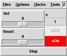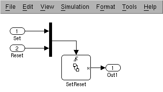
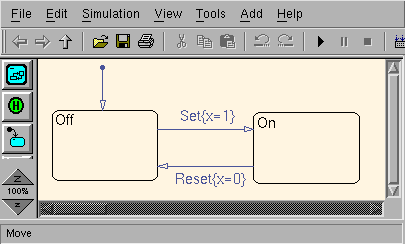
Figure 1: A simple Simulink/Stateflow chart


Consider the very simple Stateflow chart shown in Figure 12.
Figure 1: A simple Simulink/Stateflow chart
% sf2lus SetReset_r13.mdl -o SetReset_r13.lusThe Lustre nodes are called
sf_<CID> where <CID> is the
id field in the Stateflow chart entry.
This node looks as follows, noting that the first Stateflow chart in the model
almost always has number 2:
-- graph id=11 name=22,GCTOP
node sf_2(Set, Reset: event) returns(x: int);
var ini, lv5, lv5_1, lv6, lv6_1, lv7, lv7_1, ok22, ok22_1, ok22_2, ok22_3,
    s3, s3_1, s3_2, s3t, s4, s4_1, s4_2, s4t, trm: bool; x_1, x_2: int;
let
...
This is valid Lustre code and can be compiled with Lustre:
lustre SetReset_r13.lus sf_2 -o SetReset_r13.oc -0
poc -loop -o SetReset_r13.c SetReset_r13.oc
gcc -c SetReset_r13.c -o SetReset_r13.o
gcc -c SetReset_r13_loop.c -o SetReset_r13_loop.o
gcc SetReset_r13.o SetReset_r13_loop.o -o SetReset_r13
The resulting program can be run:
% SetReset_r13
##### STEP 1 ##################
Set (true=1/false=0) ? 0
Reset (true=1/false=0) ? 0
x = 0
##### STEP 2 ##################
Set (true=1/false=0) ? 1
Reset (true=1/false=0) ? 0
x = 1
##### STEP 3 ##################
Set (true=1/false=0) ? 0
Reset (true=1/false=0) ? 1
x = 0
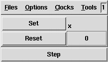
Alternatively, we can simulate the code with Luciole:
% luciole SetReset_r13.lus sf_2resulting in something like the following:
id numbers.% sf2lus -names -states_visible SetReset_r13.mdl -o SetReset_r13.lusresulting in the following Luciole display:
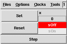
s for
a terminal state and sg for a state containing substates when there is
hierarchy or parallel states.
Note that these are abbreviated names so, for example, ``state'' is shortened to
``s'' and ``subgraph'' to ``sg''.
Use the -long_names option to generate the full names which results in
voluminous output even for small charts.
Note also that with -long_names the chart names become
stateflow_<CID>.-temps_visible or
-locals_visible options which attempt to dump the entire internal state of
the working chart3.
For example: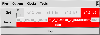
sf_2_lv5) which indicate which transition was traversed on the
previous step.-input_bools_ints which transforms input booleans into integers.
Note that this does not work for input events but Stateflow processes one
event at a time so this restriction is not relevant unless, for example, one is
model-checking the code.
In any case, events can be turned into integers using the -sends option
discussed in Section 3: